Helios® M-DOTS™ Multi-bands Digital Optical Transport System
Flexible Wireless Coverage and Capacity
Overview
Helios® Multi-Band Digital Optical Transport System (M-DOTS™) is the most flexible, scalable and complete solution for addressing coverage and capacity needs for cellular and public safety wireless network. The M-DOTS™ improves wireless network coverage and capacity by extending services from existing cell sites, to hard-to-reach areas by digital CPRI distributing coverage from a centralized radio suite.
Utilizing a centralized digital CPRI distributed architecture, Helios® M-DOTS™ is a two-tier architecture consisting of the Optical Master Units (OMUs) and Optical Remote Units (ORUs). RF signals from Base Stations, off-air, BDAs or combination thereof can be received. In the case of off-air feed, the OMU has the option to combine the functions of the off-air Repeater and OMU to provide transmission and distribution of radio signals. The signal is filtered and then converted to a digital CPRI data stream. The digital CPRI packet data stream is transported via single mode fiber and received by the ORUs. The ORUs then convert the digital CPRI packet data stream back to RF and amplify the signal for delivery to the antennas. On the reverse path (uplink), the ORUs and OMU perform the inverse functions and delivery the signals back to the corresponding off-air antenna, BDAs or Base Stations.
The all-digital platform with ultra-wide bandwidth RF front-end design and modular architecture enables multiple band/technologies/operator and network topologies including star, chain and hybrid to cater to different deployment scenarios. These network topologies provide reduced fiber plant usage and installation cost, and effective fiber loop redundancy configurations.
The M-DOTS™ flexibility and scalability offers service provider an optimal solution for multiple applications, such as dense urban centers, dense suburban areas, campuses, enterprise buildings, subways and tunnels. The M-DOTS™ digital CPRI distributed architecture and small form factor allow service providers to cost-effectively increase coverage and capacity in these hard-to-reach areas.
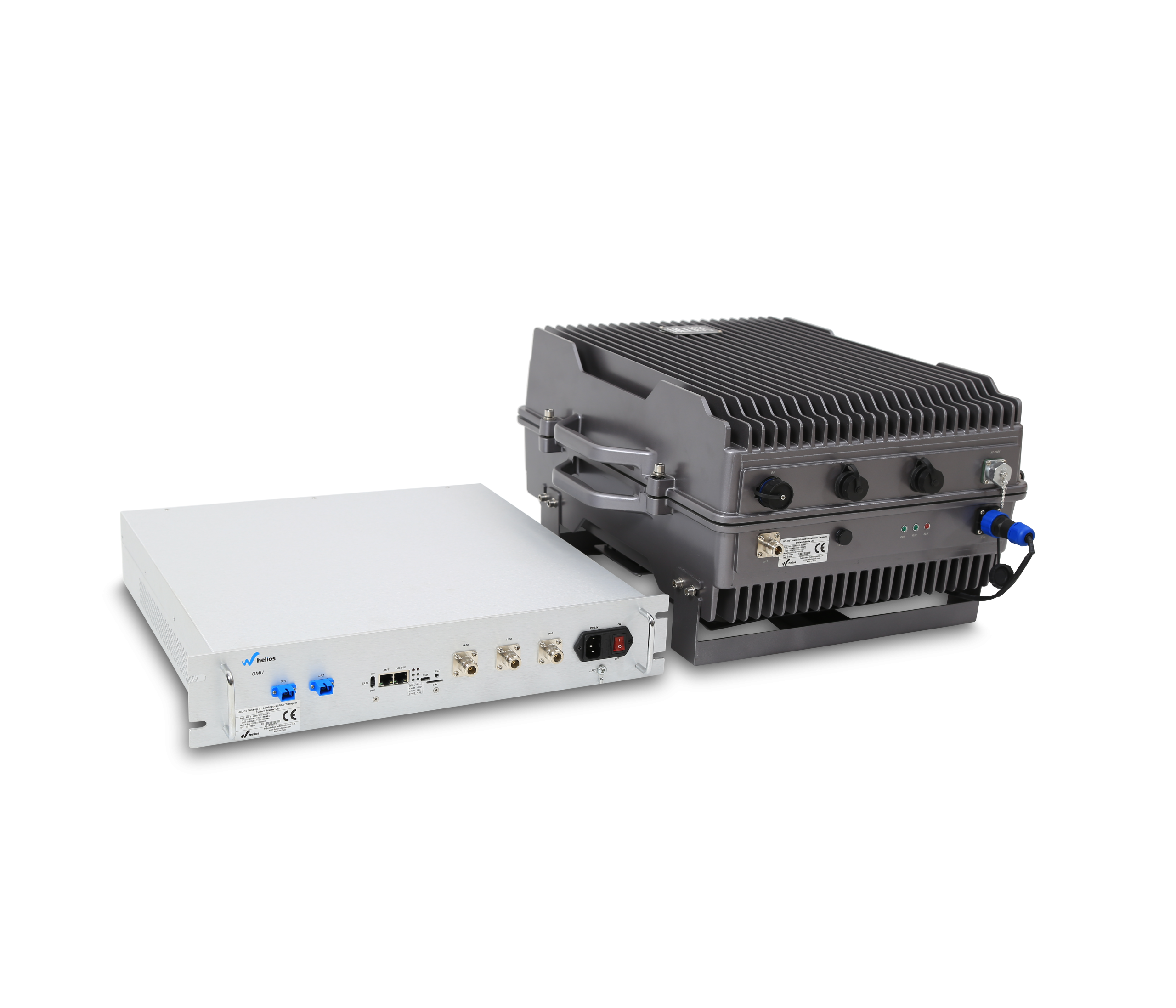
System Architecture
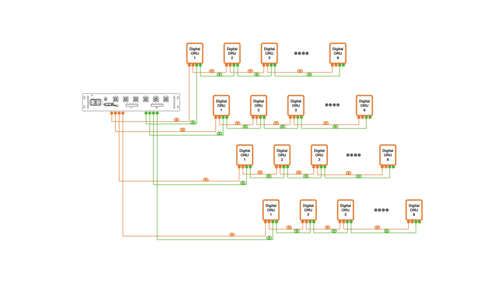
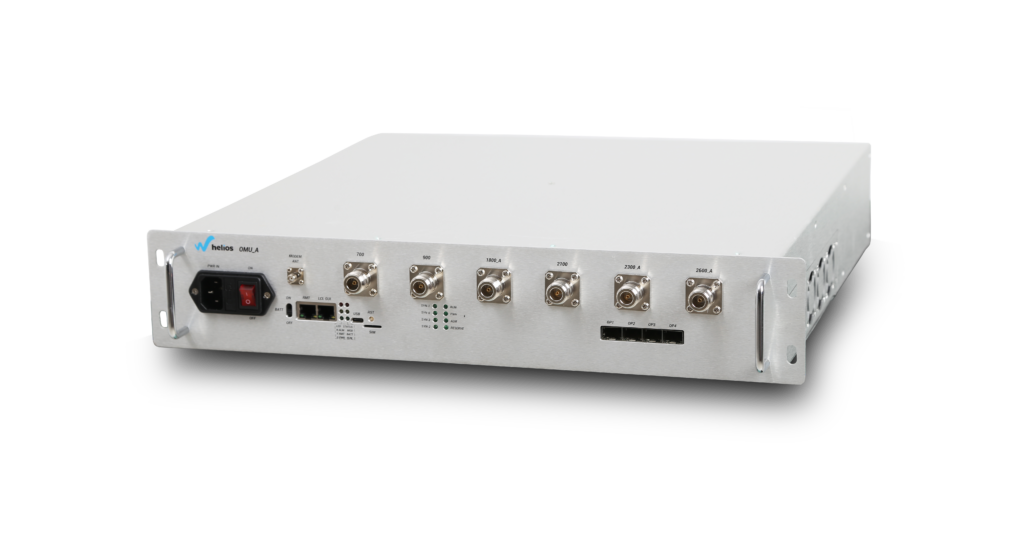
The 19″ rack-mountable M-DOTS™ – OMU is typically located at a Base Station or a facility housing a suite of Base Stations. On the forward path, the OMU receives the RF signals from the BTS and digitizes the designated RF bands and digitally transports them over single mode fiber to the Remote Units. On the reverse path, the OMU receives the digitized RF signals from the Remote Unit and converts them back to RF for the BTS.
With ultra-wide bandwidth RF front-end design enables each M-DOTS™ OMU supports up to six RF bands. All each RF band can be configurated to be FDD or TDD mode in factory and supports up to 100MHz bandwidth RF signals in order to be capable of simulcasting signals for multiple bands/technologies/operators and MIMO, even ultra-wide bandwidth requirement for future 5G NR TDD.
Each M-DOTS™ OMU has four 10Gbps SFP+ digital optic ports and supports up to 32 ORUs by star, chain, ring and hybrid network topologies, even up to 196 ORUs by adding OEUs in some scenarios, such as subways and tunnels.
The OMU utilizes an embedded WEB management system for system configuration and network monitoring. The embedded WEB management system collects alarm information from both OMUs and ORUs. For multiple link deployments, multiple cascade OMUs networked together at same BTS site.
Features & Benefits
- 19″ rack-mountable design
- Full digital software and hardware platform with Ultra-wide RF front-end design and enables multiple bands/technologies/operators and MIMO, even ultra-wide bandwidth requirement for future 5G NR
- Supports up to six RF bands and up to 100MHz bandwidth RF signals per bands
- Each RF bands can be configurated to be FDD or TDD mode in factory and supports synchronization for TDD-LTE multi-Channel
- Ultra-wide band (400MHz DL and 400MHz UL on one fiber core, dual cores double to 800MHz DL and 800MHz UL) adaptable to all Global Communications Bands, 2*2 and 4* 4MIMO, now and future 5G NR
- WEB GUI based Spectrum Analyzer (Option)
- 2*RJ-45 Port for Local Control and Alarming on an IP Web Browser GUI
- Each M-DOTS™ OMU has four 10Gbps SFP digital optic ports and supports up to 32 ORUs by star, chain, ring and hybrid network topologies, even up to 196 ORUs by adding OEUs in some scenarios, such as subways and tunnels
- SNMP V2 & V3 support with a MIB File
- Supports Remote Control via wireless modem
M-DOTS™ Optic Remote Unit – ORU

The M-DOTS™ – ORU utilize a modular design, which support up to six bands. Each ORU allows for easy field access and future upgrades to add RF bands or technologies by simple HotSwap.
Typical mounting options for the ORU include pole-mount, wall-mount and sub-terrain vault-mount. And the enclosure of the M-DOTS™ – ORU is fully sealed IP-65 rated with unique 250mm depth compact design, which minimizes maintenance and is ideal for harsh environments. The ORU owns a hot-swappable external Fan Tray with four high-performance temperature-controlled fans with IP65-rated waterproof design, it is ideal & flexible field replaceable units (FRUs) for increasing ventilation for ORU, better airflow keeps device cool and helps boost system performance and avoids costly equipment failures.
On the forward path, the ORU receives the digitized spectrum from the OMU and converts the spectrum back into RF to be distributed via an externally mounted antenna system. On the reverse path, the ORU digitizes the designated RF spectrum and digitally transport it over single-mode fiber to the OMU.
Features & Benefits
- Flexible & scalable architecture by modular design
- Full digital software and hardware platform with Ultra-wide RF front-end design and enables multiple bands/technologies/operators and MIMO, even ultra-wide bandwidth requirement for future 5G NR
- Supports up to six RF bands and up to 100MHz bandwidth RF signals per bands
- Each RF bands can be configurated to be FDD or TDD mode in factory and supports synchronization for TDD-LTE multi-Channel
- RF composite DL Output power up to +43dBm per Band
- Digital optical path fault auto-detection
- RJ-45 Port for Local Control and Alarming on an IP Web Browser GUI
- Unique compact IP-65 rated ORU design with max 250mm depth for pole and wall mounted
- Flexible IP-65 rated waterproof Hot-swappable external Fan Tray with four high-performance temperature-controlled fans for increasing ventilation and better airflow
- Redundancy additional internal switch power is available for critical-mission application
- Compatible with HELIOS® DTFMS™ Radiating Cable Distance-to-Fault Measure System (Option)
Technical Specifications – OMU
Technical Specifications – ORU